Spring is here and it’s irrigation start-up season! It’s great to be back to work but as with every season there are systems that just don’t work as they should. Troubleshooting can be frustrating and take valuable time away from other jobs. If the system is through a manufacturer you are unfamiliar with sourcing the resources you need quickly can feel impossible.
That’s why we’ve asked Doug Armour, Central’s Commercial Irrigation Technical Manager, to share his insight on what to do when an irrigation system is not working properly. Armour is certified by the Irrigation Association as a Landscape Irrigation Water Manager, in addition he holds certifications with Hunter and Rain Bird, and has been factory trained with Tucor. He is an excellent resource for any technical questions about irrigation systems and for troubleshooting systems that are not working properly.
From Doug:
Central’s marketing department asked me to write a piece on troubleshooting irrigation systems. As soon as it was time to put pen to paper, the calls started coming from the field to troubleshoot systems in real life. Since our seasonal sprint is starting, I want to keep this piece very direct and as simple as possible.
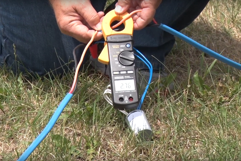
When a watering zone will not activate, the best tool you can use for troubleshooting is a multimeter. It is a critical piece of equipment that every irrigation contractor truck should have. A multimeter is an inexpensive piece of equipment and its capable of troubleshooting a variety of problems with an irrigation system, including AC and DC voltage, and resistance. It can help identify issues with solenoids, valves, field wiring, and controllers.
This piece of equipment is really worth the investment and will pay for itself time and again. Get one. Armada has several multimeters to choose from, you’ll be able to find one that makes sense for your business. If you also install landscape lighting, consider getting a true RMS multimeter because you will be able to use it for both irrigation and landscape lighting.
Here are a few basic terms to know and understand when troubleshooting a system:
- AC volts (VAC) – Alternating Current, this is household voltage. Most irrigation solenoids operate on AC voltage.
- DC volts (VDC) – Direct Current, the normal source is a battery. DC voltage is polarized, meaning that there is a positive(+) and a negative(-), sometimes referred to as ground. Note: The meter must be connected properly to prevent meter damage, the RED lead is(+), and the BLACK lead is(-).
- Resistance (ohms Cl) – A measurement of how difficult it is for the current to flow through the electrical system. This is very similar to friction loss through a piece of PVC pipe.
Resistance is the most useful function for troubleshooting irrigation systems. For irrigation applications, a solenoid is considered to be good if its resistance is between 20 -60 ohms. Terms to understand under resistance are as follows:
- Short – when the resistance measured is below 20 ohms for a single solenoid. This allows excess current to flow through the circuit breaker or fuse. If the amount of current exceeds the rating of the devise, it will open, therefore stopping the 24 volts to the valves.
- Open – when the resistance is above 60 ohms, the flow of current to the solenoid is reduced. Think of this as having a rock lodged in the mainline of a sprinkler system. The resistance may increase to the point that the solenoid does not get enough voltage to operate.
Using the Multimeter
Make sure to take the time to read the instructions on your multimeter. Knowing how to operate a meter will save considerable time when testing the wiring on a job site.
Basic steps for using the meter:
- Disconnect the common wire(s) from the terminal strip on the controller.
- Turn the dial to the resistance or Ohms setting (this looks different on every meter)
- Connect one of the meter leads to the common wire, not the controller common terminal.
- Touch the second meter lead to each of the station terminals, and record the resistance readings.
Compare your readings to the acceptable range of 20 – 60 ohms. The reading will give you insight into the problem. See the possible outcomes and recommended action below:
Acceptable Range:
If the measurements are within the acceptable range (20 – 60 ohms) then the electrical circuit for that station is good. Just note, that this test only inspects the condition of the wiring, the station may not operate properly because of controller and/or valve problems.
A short:
If the resistance range is below 20 ohms (a short), proceed to the valve and disconnect the solenoid from the field wires. Test the resistance of the solenoid only. If the measurement is still low, then the solenoid must be replaced. If the solenoid resistance is acceptable, then the short is in the field wiring itself (two solenoids connected to the station can also produce a low reading). Wire tracing equipment should be used to locate the problem.
An open:
If the resistance is above 60 ohms (an open), test the solenoid without the field wires connected. Replace the solenoid if its resistance is still above 60 ohms. More than likely, the solenoid will test within proper limits of between 20 – 60 ohms.
If the solenoid is good:
Cut out the wire connectors and connect the station and common wires together at the valve location. From the controller, re-test the resistance without the solenoid in the circuit. The resistance should now read very low, possibly 5 ohms or below since only the resistance of the field wires is being measured. If the resistance is this low, then the problem was a faulty wire connector. Install new waterproof wire connectors on the existing solenoid and test the resistance again at the controller.
What if the resistance is still high?
If the resistance is still high when the common and station wires are connected together, then there is an open somewhere between the valve and the controller, possibly caused by a faulty wire or wire connector. Unfortunately, this fault can only be found with the use of wire tracing equipment.
This final field wiring test will determine shorts directly into the earth:
In addition to the common still being disconnected, remove each of the station wires from the controller. Connect one of the meter leads to a piece of bare wire wrapped around the metal shaft of a screwdriver. Insert the screwdriver into the ground (it may be necessary to wet the ground to assure a good connection). Touch the second lead to the station wires and the common one at a time. Each of these measurements should be above 700K (700,000) ohms.
A resistance reading of below 700,000 would indicate a section of the wire has a nick in the insulation and is making contact with the earth. Wire tracing equipment should be used to locate the problem.
Transformers can also be tested using a multimeter.
Connect the meter leads to the primary winding, that Is, the transformer input wires or plug in connectors. You will either get a resistance reading or an open. A resistance reading shows the internal windings are intact, an open indicates the transformer’s internal fuse is bad and the transformer must be replaced.
The secondary winding, the transformer output, is tested the same way. Connect the meter leads to the output wires. An open indicates that the transformer must be replaced. The 20 – 60 ohm rule does not apply to transformers. It Is common to find resistance as low as 3 ohms.
A multimeter may also be used to determine what type of battery should be used in a solid-state controller.
The controller should be powered up and the battery removed from its connector. Rotate the dial to the DC V setting. There are two battery connectors, a large one (female) and a smaller one (male). Touch the red probe to the large connector, the black probe to the small connector. If the controller is designed to accept an alkaline battery, the reading will be close to zero volts. If it is designed to accept a rechargeable NiCad battery, the reading will be between 7 and 13 volts DC.
Just a reminder: never use an alkaline battery in a controller designed to accept a rechargeable battery. Also, do not use rechargeable alkaline batteries in solid-state controllers.
As mentioned earlier, troubleshooting can be very frustrating and not always straight forward. A system might have more than one issue. Rely on Central to help, whether it’s questions about troubleshooting or installation, showing you how to use specific equipment, or sharing insight and recommendations on the newest technologies. We stay at the leading edge of the industry and we’re ready to help you grow!
About Doug Armour
 Doug Armour is certified by the Irrigation Association as a Landscape Irrigation Water Manager, in addition he holds certifications with Hunter and Rain Bird, and has been factory trained with Tucor. He is an excellent resource for any technical questions about irrigation systems and for troubleshooting systems that are not working properly.