Common two-wire problems include zones that do not start and/or have a shorted wire path. Most of these issues are caused by a bad splice, nick or break in the wire path. Many of these issues can be avoided and even future-proofed, just by installing the right products. The #1 Rule is to only use wire and splice kits designed for two-wire systems. No exceptions! The wire must be insulated solid strand wire with an outer jacket. This outer jacket provides additional durability during installation. Paige P7072D Wire, in either 12 or 14 gauge, is the ideal wire to use in all of your installations. Keep in mind that the gauge of a wire is dependent on the length of the overall wire path and number of decoders. If you choose to use a different brand of wire, be sure that the wire has equivalent specifications & properties! Often times, each manufacturer has different specifications.
Pro Tip: Always use different color wire to easily identify different wire paths. It makes a big difference if servicing or add-ons are required in the future.
Tips for Conduit, Valve Boxes & Splicing
Consider installing two-wire paths in conduit on commercial projects, especially for multi-phase construction projects. Conduit helps protect the wire and makes replacing sections easier. Splice kits should be 3M DBR/Y-6 or equal. They are rated for two-wire voltage; conventional splice kits are not. Use DBR/Y-6s for all splices – especially between the two-wire and decoder & between the decoder and solenoid. Never reuse splice kits if they are removed for any reason. DBR/Y-6s are more expensive than conventional wire kits, but rest assured that using them properly will avoid issues and lessen the need for troubleshooting in the future.
- If possible, avoid splices between valve boxes
- Splices should have 2 -3 feet of slack in the wire on both sides.
- Splices must be in valve boxes for easier location later.
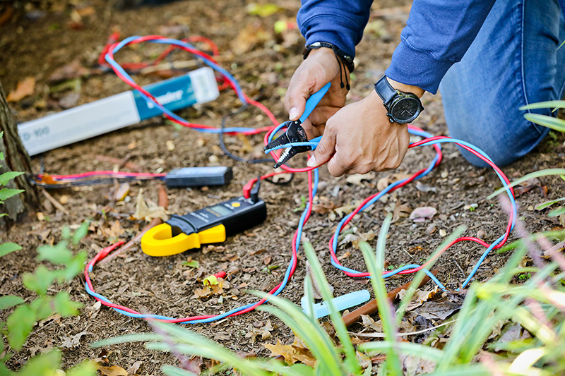
When two-wire problems do occur, there are three essential tools you must have:
- An as-built drawing showing the two-wire path, decoders, and valves. Decoder addresses and station numbers must be called out.
- A clamp meter that reads in milliamps.
- An understanding of the controller’s diagnostic capabilities and the milliamp draw of its decoders.
When troubleshooting, always start with the easy stuff. If zones are not operating, run through the controller diagnostics first. Most controllers can identify non-responding decoders. Once identified, locate the decoders on the as-built. You may see a pattern; perhaps they are grouped together, downstream of one defective splice. This is the obvious benefit of an accurate as-built. If the issue still has not been found, then move to the field and check splices, decoders, and solenoids. Chances are the issue will be with a splice. It could be very visible, such as two disconnected wires or it may not be so obvious. In this case, it is often easier to replace the kits in order to solve the problem. If the splices are ok, check the decoder and the solenoid.
If still in doubt, remove the decoder and solenoid and reconnect them at the controller. Then activate that station. This removes the wiring and splices from the equation. Some manufacturers have handheld testing units to determine if the decoder is working correctly, all without removing it from the wire path.
When a clamp meter is used on the wire path, it will record the downstream milliamp draw. You must know the quantity and draw of each decoder to understand what a correct reading should be. If the draw is less than it should be, there is an open wire between your location and the end of the wire path. If it is more than it should be, there is a leak to a ground which is caused by a defect in the wire or in a splice.
Another common problem is a short on the wire, shutting down the controller entirely. This happens when the two wires are exposed and in contact with each other. The controller display will indicate a short. First disconnect the wire path from the controller. If the short indication stays, the problem is within the controller board, and it must be replaced.
If the short is in the field, consult your as-built and disconnect the wire path approximately in the middle. If the short display goes away, the short is downstream of that location. If it does not go away, it is closer to the controller. Keep splitting the difference until the short is isolated to a relatively small area. Chances are, you will find a defective decoder or surge arrestor in that area.
Please contact your Central account manager for more information on troubleshooting your specific project and controller. We are here to assist and educate to make you more efficient and profitable.
About Dave Shane
Dave has more than three decades of experience in the irrigation industry in both distribution and manufacturing roles. He specializes in commercial project solutions with an emphasis on controls to meet complex requirements. He is an excellent resource for any technical questions about irrigation systems and finding the right solutions for efficient irrigation systems.